Background
Beam Camber or "Crop" is the term used for the curvature of deck beams or coachroof beams in a yacht – or a commercial vessel for that matter.
Camber, or crop is usually expressed as a rise of x in a width of y or in percentage terms, where x is given as a percent of y.
Traditionally, and still today in the USA, this would be expressed as, say, ½" in 1'. Meaning that for every 1' in width the camber will rise ½". Usually the total width of the beam is taken, with the highest point being in the middle. So, for a beam 6' wide, with a camber of ½" in 1', the camber would be 6 x ½" = 3", which would be the height rise at the centre.
In the metric system camber is usually expressed in percentage terms. So ½" in 1' = ½" in 12" = 1/24 = 4.2%. Usually one sticks with round numbers, so the camber would be expressed as 4% or 5% etc. At 5% for example, a beam of width 2000mm would have a rise of 2000*5/100 = 100mm at the centre.
In older designs camber tends to be flatter than in more modern designs. So while older designs would often have a camber of ½" in 1' (1/24 , 4.2%) to ¾" in 1' (1/16, 6.25%), more modern designs tend to have rather more camber ranging from 7% to 10%. It is also common to give coachroof tops a little more camber than the decks – both for better headroom and appearance.
Having established the actual camber, we now have to establish how to draw it – what shape should it be to arrive at the centre height. Traditionally, boatbuilders used a graphical method to draw beam cambers when laying off (lofting). This gives a parabolic camber, and tends to produce nice fair surfaces in general. The image below illustrates how this is done:
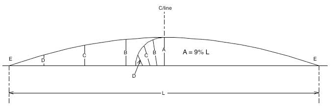
The illustration shows a beam of length L with a rise of A – A being 9% of L in this case (about 1" in 1'). The basic process to create the camber curve is as follows:
- Strike an arc, radius A
- Divide the arc into equal segments (4 in this example)
- Divide the base of the arc into the same number of equal segments
- Join the base segments to the arc segments – lines B. C & D in this example
- Divide the beam base L into equal segments (in this case 8 – 4 each side)
- Set out the lengths B, C & D each side
- Join E-D-C-B-A-B-C-D-E in a curve – which will be the beam camber shape
The Aim of the Script
Many Naval Architecture programs use NURBS (Non Uniform Rational B-Splines) to create hull shapes. And as usually organized these are very good at drawing hull shapes and fairing them. But usually they are not good at drawing to a very specific curve like a camber. However most programs do have the possibility of creating a surface from a set of data points in a text file
The object of the BeamCamber script is to be able to create a series of beam cambers in RealCADD and save the resultant data in a text file that could be exported directly to a naval architecture program. In my case I wanted to be able to export to Prefit, which is part of the MaxSurf suite of programs. But the data can be imported into any 3D program that can read a text file.
As well as creating full camber surfaces – that is where the beams run full width from one side to the other, we need to also create part cambers (in particular for the sidedecks of vessels), where the resultant surface was just part of the full camber but matched the full camber shape exactly. This script is, appropriately named SideDeck
BeamCamber & SideDeck were created by my colleague Tony Poulston (who did all the coding) and myself; we are also very grateful to Eric Pousse for adding the features we needed to the RealCADD scripting facility as an when we needed them – without this BeamCamber and SideDeck would not be possible. The extra features are contained in RealCADD version 4.70b3 and this is needed for BeamCamber and SideDeck to work.
While BeamCamber and Sidedeck are fairly specific to marine vessel design, we envisage the possibility of adding NACA foils (airplane wings, yacht keels, airplane and yacht rudders etc) and other specific curves to the suite of scripts. BeamCamber, SideDeck and the future scripts can be used simply to produce those curves directly in RealCADD as a 2D shape - or provide the data to be used to produce a 3D surface.