Scale is the relationship between the size of an object on a drawing and the size of the drawn object in real life.
So if you draw an object at 1/10 scale, on the drawing it will be one-tenth of the size of the object in real life. Thus, for example, a real-life 1000mm line will be one-tenth of that size – so 100mm actual physical length – on your drawing.
Maps are perhaps the most familiar example of this concept – where, say 1 cm on the map may represent 1 km on the ground (a scale of 1:100,000); or 1" on the map may represent 1 mile on the ground (a scale of 1:63,360).
With a map as with an engineering, design, or architectural drawing, the scale has to be chosen so that drawn object will fit on to a reasonably-sized piece of paper (or similar medium), so as to be useable.
Even in today's digital world, most designs end up being printed in some way or another, so that clients, builders, planning departments etc. can look at them, work from them, comment on them and so on.
Traditionally drafting technicians would choose a scale for their drawings so that what they were drawing would fit on the paper they were drawing on. And within various disciplines conventions emerged for the scales normally to be employed, paper sizes to be used and so forth. And furthermore, authorities (like planning authorities, code enforcement etc.) would sometimes dictate the scale to be used for presented drawings.
With the development of CAD, two basic concepts developed:
Scale: This follows the traditional concept. You select the scale of your drawing based on the size of paper (or other medium) on which it is going to be printed, or indeed the size you want it to be displayed at 100% zoom. This is also called drawing in "Paper Space" in some CAD programs.
Advantages:
- For a designer coming from a traditional drafting background, the concept of scale comes quite naturally.
- The screen version and the printed version of the drawing are identical.
- Printing is simple and straightforward, usually at the default of 100%.
- When/if the drawing is printed it will be true to scale – or at least as true as the chosen medium will allow.
- Text and dimensioning can be arranged to be proportionate to what is being drawn and remain as drawn when printed.
- The drawing on the screen is a reasonable physical size, so you can scroll around more easily and work at a reasonable magnification.
Disadvantages:
- You have to work out what size your drawing is going to be based on the size of what you want to draw before you start to draw.
- If for some reason the drawing gets larger and outgrows the page, then you have to rescale it, or increase the size of the paper.
- You may need to use different size text from drawing to drawing where scales vary widely.
Full size: With this system everything you draw on on your computer is drawn at full size (i.e. a scale of 1/1). Only when you come to print a drawing is it scaled to fit the size of the medium on which you are going to print it. This is also called drawing in "Model Space" in some CAD programs.
Advantages:
- You can just start to draw without worrying about the drawing size or scales.
- All your drawings are the same scale (1/1).
- A very standard setup of line weights, text sizes and so forth.
- If you are not fussed about the scale on the printed version, then printing is usually very easy (through a "fit to page" command).
Disadvantages:
- It can be more complicated when you come to print, or prepare the drawing for printing.
- Drawings of big objects are physically big, so you have to scroll about more or work at smaller magnifications.
- Text, dimensioning and labelling, line weights etc. can get a bit complex to manage, especially when printing a drawing of a very large object (or indeed a very small object) relative to the paper size.
RealCADD uses the Scale or Paper Space mode: objects are drawn to a chosen scale. The scale is most often chosen so that what you draw will fit on a certain size piece of paper (or other printing medium).
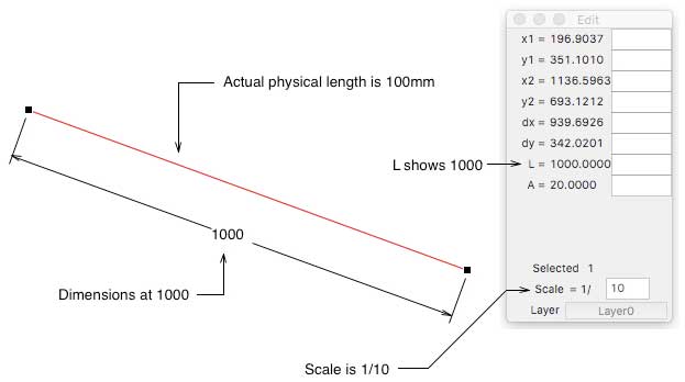 Take our real-life 1000mm line example from above, drawn at 1/10 scale.
As you draw it the edit pallet will show its real-life length, getting close to 1000mm as you drag; and once you have adjusted it, it will show (in the Edit pallet) as 1000mm long in the "L =" field.
If you used the Command Line to draw the line (in, say, L-mode) you would enter 1000 in the L box (plus the angle in the A box – in this example 20º).
So even though the line is in fact only 100mm in actual length, RealCADD knows it as 1000mm by virtue of the chosen 1/10 scale. If you dimension it, RealCADD will dimension it as 1000mm long.