 Select and click under the Window menu for the pallet to be displayed and active. Active pallets are marked with a ✓ in the Window menu. The menu displayed shows the pallets that I usually have active all the time.
Initially RealCADD will open with a new Plan – "Untitled 1" – which will be displayed at the bottom of the Window menu. As more drawings are opened, they will add to the list. To move from one to another, simply click the one you want. The current drawing will be ticked.
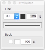
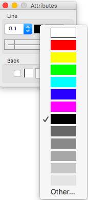
The Attributes pallet, shown to the far right, basically controls the appearance of objects. This is the new 4.90 version of the Attributes pallet; RealCADD users with earlier version will see a different pallet, although the basic functions remain the same. The 4.90 version encompasses enhanced arrow functions and a full colour spectrum pallet. We'll take the various attributes from top to bottom.
Line
 Thickness
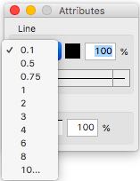
The line weight box displays the thickness of a selected the line or path of an object in pixels. This applies to all objects (rectangles, ovals, arcs, polygons and splines) as well as just lines. Clicking the box reveals the drop-down menu of available line weights as shown on the right.
 To change the thickness of a line or other object, select it and then simply select the required line weight from the drop-down menu. Line weight does not affect text.
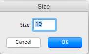
The final line thickness (10... in the image of the drop-down menu) is editable. Clicking it brings up the small pane (shown right). Entering a number in the Size box (which will be the line thickness in pixels) gives a one-off line weight available for that drawing. It doesn't change the basic line thickness menu (created in Edit >> Line thickness...).
Colour
 The central box shows and controls the colour of the lines making up objects. It also controls the colour of text.
If you select an object, the colour box will show the colour of the object's lines. To change the colour, click the colour box to display a pallet of basic colours and greys (near right) and select a new colour or grey: the colour of the object's lines will change to the selected colour. The same applies to text – change the colour of text in the same way.
If you wish to select the colour of lines before you draw an object (or the colour of text before you enter it), simply click the colour box and select the colour you want to use.
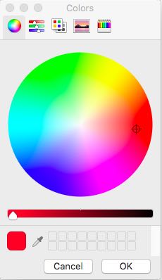
Clicking "Other ..." at the bottom of the pallet will access full colour spectrum pickers (far right), giving access to millions of colours and greys, via five different pickers (spectrum, sliders, crayons etc.). You can select which picker you want by clicking their icons along the top of the pallet. The current colour picked is displayed in the box bottom left. Clicking the pen next to the box produces a magnifier which, if you move over a drawn object and click, will change the picker to that colour. You can use this to discover what colour an existing object is drawn in for example.
To change the lines of an object to "Other..." colours, select the object, click "Other...", select your colour shade and click the OK box: the object's lines will change to the selected colour. The same applies to text – change the colour of text in the same way.
As with the basic colours, to select from the full spectrum colours of lines before you draw an object (or the colour of text before you enter it), click "Other..." and select the colour you want to use, and click OK.
Experiment and enjoy!
Transparency
The % box controls the transparency of the selected colour. 100% (the default) is totally opaque – not transparent at all – you can't see anything through it. 0% would be completely transparent – so you wouldn't see the object at all and would see everything completely through it. In fact RealCADD, quite reasonably, has a minimum of 5% transparency. As you decrease the percentage, objects under the transparent object become more and more visible. In practice, transparency is more commonly used with filling an object rather than the actual lines that make it up.
To change the transparency of an object's lines, or the transparency of text, enter a number in the percentage box and hit the ⏎ (Enter/Return) key.
Tip: The transparency percentage persists, so it is better to change it back to 100% before you draw something else.
 Line Style
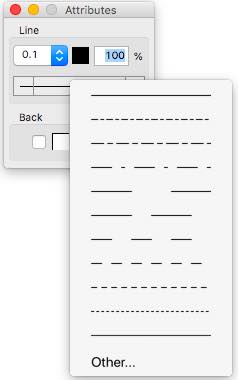
The long box displays and controls the style of the lines making up an object (solid or dashed) and where appropriate, the type of arrows on the ends. The style is shown in the central portion and the arrows in the smaller boxes to the left and right.
If you select an object, the line style box will show the style of the objects lines and any arrows applied. To change the style, click the central part of the box box to display the available styles and select a new style; the style of the object's lines will change to the selected style.
To pre-select a particular line style before drawing a line or object, click the central part of the box to display the available styles and click the one you want.
Styles (solid or dashed) can be applied to the lines making up all objects – rectangles, rounded rectangles, polygons, splines, circles, ovals, arcs and ellipses.
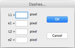 Clicking Other... will bring up the menu shown to the right. This allows you to create one-off dashes specific to the current drawing. This will not change the standard dashes menu (created in Edit >> Dashes...). The components are:
L1 is the length of the first line
e1 is the gap between the first and second lines
L2 is the length of the second line
e2 is the gap between the second line and the start of the repeat of the first line
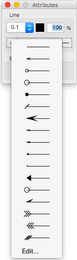 Arrows can be applied to the start of a line, the end of a line, or both. Clicking the left hand box displays the arrows for the start of the line; clicking the right hand box displays the arrows for the end of the line. New in 4.90, different arrows can be applied to each end and can be applied to the ends of lines, splines, polygons, arcs and ellipses.
To add an arrow to the start of a line (or spline, polygon, arc or ellipse) – or change an existing arrow to a different one – select the object, click the left hand box and drag down the drop-down menu of arrows to the one you want and click (or let go of the mouse button) to apply the selected arrow. To add or change the arrow on the end of a line, do the same using the right hand box.
To remove an arrow entirely choose the first option in the drop-down menu (the plain line).
To pre-select a particular arrow before drawing a line or object, click the left hand (for line start) or right hand (for line end) box to display the available arrows and click the one you want.
 If none of the arrows are quite what you want, you can use the "Edit..." function at the bottom of the drop-down menu (from either the left or right hand box).
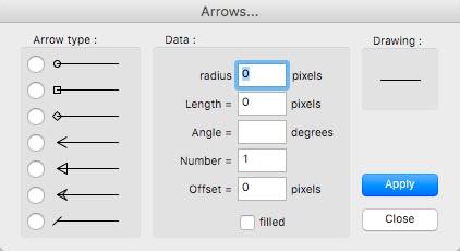
There are two modes to this. The Limited Edit mode displayed to the right simply allows you to produce a new arrow that is specific to the line or object selected. The new arrow won't get added to the arrow drop-down menu for that drawing, nor will it change the of the program-wide standard arrow menu. This is the mode described here.
The Full Edit mode, which changes the program-wide standard arrow menu is usually and preferably accessed from Edit >> Arrows…. However it can be accessed from this "Edit..." function under two circumstances:
– A drawing tool to which arrows can be added is selected, but before drawing anything.
In the Limited Edit mode, all seven arrow types are available for editing:
Square or rectangle
Diamond
Open arrow
Triangle
Classic arrow
Line
The Data section controls the shape of the arrows, whether they are filled or not, and how many repeats of the arrows there are. The information varies a little depending on the arrow type.
Circle or oval: The first two boxes read Radius X and radius Y and control the x and y radii of the arrowhead. If they are the same the arrow will be a circle; if they are different it will be an oval. Angle is not used and is dimmed out. Number controls how many arrowheads there will be (default is 1). Offset controls how far apart multiple arrowheads will be (default is 0). The "filled" checkbox controls whether the arrowhead is filled or not.
Square or rectangle: The first two boxes read Dim X and Dim Y and control the x and y dimensions of the arrowhead. If they are the same the arrow will be a square; if they are different it will be a rectangle. Angle is not used and is dimmed out. Number controls how many arrowheads there will be (default is 1). Offset controls how far apart multiple arrowheads will be (default is 0). The "filled" checkbox controls whether the arrowhead is filled or not.
Diamond: The first two boxes read Dim X and Dim Y and control the x and y dimensions of the arrowhead. If they are the same the diamond will be a square; if they are different it will be a rectangular. Angle is not used and is dimmed out. Number controls how many arrowheads there will be (default is 1). Offset controls how far apart multiple arrowheads will be (default is 0). The "filled" checkbox controls whether the arrowhead is filled or not.
Open arrow: The first two boxes read Dim 1 and Dim 2 and control the lengths of the two arms of the arrowhead. Angle controls the angle each arm makes to the line. If the angle is positive, then Dim 1 is the top arm and Dim 2 is the bottom arm; if the angle is negative Dim 1 is the bottom arm and Dim 2 is the top arm. Angles greater than 90º will produce a backwards-facing arrow. Number controls how many arrowheads there will be (default is 1). Offset controls how far apart multiple arrowheads will be (default is 0). The "filled" checkbox controls whether the arrowhead is filled or not. The arrowhead fills from the tip of one arm to the tip of the other, so in fact it appears the same as the Triangle when filled.
Triangle: The first two boxes read Dim 1 and Dim 2 and control the lengths of the two arms of the arrowhead. Angle controls the angle each arm makes to the line. If the angle is positive, then Dim 1 is the top arm and Dim 2 is the bottom arm; if the angle is negative Dim 1 is the bottom arm and Dim 2 is the top arm. Angles greater than 90º will produce a backwards-facing arrow. Number controls how many arrowheads there will be (default is 1). Offset controls how far apart multiple arrowheads will be (default is 0). The "filled" checkbox controls whether the arrowhead is filled or not.
Classic arrow: The first two boxes read Dim 1 and Dim 2 and control the lengths of the two major arms of the arrowhead. Angle controls the angle each major arm makes to the line. If the angle is positive, then Dim 1 is the top arm and Dim 2 is the bottom arm; if the angle is negative Dim 1 is the bottom arm and Dim 2 is the top arm. Angles greater than 90º will produce a backwards-facing arrow. The inner arms adjust automatically to the angles and dimensions chosen (and can produce some odd/interesting results with different sized arms and different angles). Number controls how many arrowheads there will be (default is 1). Offset controls how far apart multiple arrowheads will be (default is 0). The "filled" checkbox controls whether the arrowhead is filled or not.
Line: The first two boxes read Dim 1 and Dim 2 and control the lengths of the two arms of the arrowhead. Angle controls the angle each arm makes to the line. If the angle is positive, then Dim 1 is the top arm and Dim 2 is the bottom arm; if the angle is negative Dim 1 is the bottom arm and Dim 2 is the top arm. Angles greater than 90º will produce a backwards-facing arrow. Number controls how many arrowheads there will be (default is 1). Offset controls how far apart multiple arrowheads will be (default is 0). The "filled" checkbox is not used and is dimmed out.
The "Drawing" box shows the effect of the changes. Once you are happy with the new arrow style click the "Apply" button and then "Close". Your edited arrow will be applied to the selected line or object.
Tip: Though it won't show in the arrow segment of the lines style box (it will show plain) the edited arrow will continue to be drawn on all new lines or objects until you either select for no arrow or a different arrow. To draw more lines or objects with the edited arrow at a later date (on the same drawing), simply select a line with that arrow on it and continue drawing. You can also use Action >> Apply attributes (⌘⌥A) to transfer the edited arrow from one object to another.
Back
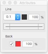 Checking the Back box, fills a selected object with whatever the Back colour is. The current fill colour (red on the image to the right) is shown in the square box to the right of the check box.
Clicking the fill colour box brings up the basic colour pallet as described for Lines above and clicking "Other ..." at the bottom of the pallet will similarly access full colour spectrum pickers.
To change the fill colour of a selected object, or to change the background colour before you fill an object, click the colour box and select a new colour.
The background colour can also be applied to provide a background for text. Simply select the text, check the Back box and select the colour.
Transparency
The % box controls the transparency of the selected colour. 100% (the default) is totally opaque – not transparent at all – you can't see anything through it. 0% would be completely transparent and everything would show completely through it. RealCADD has a minimum of 5% transparency. As you decrease the percentage, objects under the transparent fill become more and more visible.
To change the transparency of an object's fill, or the transparency of a text background, enter a number in the percentage box and hit the ⏎ (Enter/Return) key.
Transparency is particularly useful when used with a text background; but it can also be quite effective with object fills.
Tip: The transparency percentage persists, so it is better to change it back to 100% before you draw something else.