| RealCADD Cursors | |
|---|---|

|
Select cursor |

|
Object is selectable |

|
Select has found an endpoint |

|
Select has found a centre |

|
Select has found an intersection |

|
Select has found a surface (periphery) |

|
Select is in parallel mode |

|
Select can draw a parallel |

|
Lasso cursor |

|
Hand cursor |

|
Zoom cursor |

|
Text entry cursor |

|
Draw cursor |

|
Draw from centre cursor |

|
Draw by diameter cursor |

|
Draw by three points cursor |

|
Draw cursor has found an end point |

|
Draw cursor has found a centre |

|
Draw cursor has found an intersection |

|
Draw cursor has found a periphery |

|
Can draw a perpendicular |

|
Can draw a tangent |

|
Lines up horizontally |

|
Lines up vertically |

|
Lines up both horizontally & vertically |

|
Rotate or symmetry cursor |

|
Rotate cursor has found an endpoint |

|
Rotate cursor has found a centre |

|
Rotate cursor has found an intersection |

|
Cutting tool is active |
Initially RealCADD will open with a new Plan – "Untitled 1" – which will be displayed at the bottom of the Window menu. As more drawings are opened, they will add to the list. To move from one to another, simply click the one you want. The current drawing will be ticked.
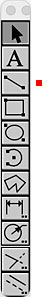 The Tools pallet accesses RealCADD's drawing, operating and modifying tools. When you mouse over the pallet, it expands to show the full range of tools available. If you have "Display helptags" enabled in Preferences, hovering over a tool for a moment will display its helptag. The basic keyboard shortcut for the row of tools is shown alongside the expanded tool pallet.
To select a specific tool click the appropriate tool row on the right-hand image and then scroll down to go to the details of how it works. The red dot  indicates which selection you are on. The descriptions are based on the standard Mac Click & Drag drawing mode. If you have selected Click & Click in Preferences, then there will be minor differences.
Tools with .. after them can be expanded to a fuller options menu by a double-click or an ⌥-click (option-click). Once a tool that has a further options menu has been selected, you can bring up the further options by hitting the space bar – this is very handy if you want to go on using the tool but merely want to change its action in some way.
All the tools have keyboard shortcuts as shown alongside the expanded tool pallet. Multiple entering the shortcut moves you along the horizontal row. A tool remains active until another tool is selected either by clicking on its icon or hitting its keyboard shortcut.
You can choose (in Preferences >> General) to have the Tools pallet expanded all the time by unchecking the "Tools" box.
With the Line, Rectangle, Oval and Arc tools, you draw the object approximately how you want it and then edit it in the Edit and Attributes pallets to get it exactly how you want it. The Edit pallet in particular is intimately bound up with drawing using the Tools and we will discuss it here along with each tool. Refer to Window >> Attributes for more details of that pallet.
Remember also that you can access all of, or your selection of, the tools by a right-click or a ⌃-left-click (control-left-click) anywhere in the drawing. The tools that are displayed are those chosen in Preferences >> "Tools" menu ... For a tool that has further options (those marked with double-dots in the Tools pallet), ⌥-right-click (option-right-click) or ⌃-⌥-left-click (control-option-left-click) as you select the tool will bring up the further options. Once you have selected the tool, if it is one that has further options, these can be accessed by hitting the space bar.
Tip: The screen version of the Tools pallet is only available when no object is selected. A right-click with an object selected will bring up the screen version of the Action menu.
With "Command Line" you draw an object (Line, Rectangle, Oval, Arc) and set its parameters on the fly as you draw. Refer to Window >> Command line.
Snap is also an important part of controlling how objects are drawn. Refer to Window >> Snap for details of how to set Snap up.
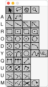
RealCADD cursors change to indicate many important aspects of using Tools; rather than endlessly discuss these changes in each section, they are listed in the table to the far right. Those that require Snap to be active are shown in green
Tip: The Surface cursor requires "Intersection" to be selected in the Snap pallet
Tip: Once you have one or more RealCADD files open, they will be displayed at the bottom of the Window menu and can be selected from there to change from one to another.
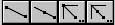 Back to top From left to right these are:
Free line by 2 tips: Keyboard shortcut L.
After selecting the tool, click on the drawing and the draw cursor will appear.
If Snap is active, as you move around the drawing, the cursor will change to indicate that it has found a snap point or is lining up with a snap point
Holding the mouse down, drag to where you want to finish the line. Holding the shift key down will constrain the line to one of your pre-set constraint angles (set in Preferences) – but not with perpendiculars or tangents. Let go of the mouse to complete the line. Adjust the line parameters (length, angle etc.)in the Edit and Attributes pallets.
As you draw and Snap is active, the cursor will change as above to indicate that the end of your line can snap to a snap point or is inline with a snap point – let go of the mouse for the end of your line to snap to the snap point, or end inline with a snap point. Perpendiculars and tangents are only active when starting to draw (but see exception for tangents below).
Additionally the cursor will change to indicate that you have intersected the periphery of an object exactly (though not on a snap point) – let go of the mouse for your line to end exactly on the object.
Free line by center and tip:
This operates in the same way as the "Free line by 2 tips", except that it starts from the centre of the line and extends equally in both directions. The cursor changes to the draw-from-centre cursor.
If Snap is active, it works just as for a "Free line by 2 tips", except that you can't draw perpendiculars or tangents.
Constrained line by 2 tips:
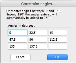 A double-click or ⌥-click (option-click) will bring up the pane to the right, where you can specify the constraint angles. Only enter angles <180º; the program automatically adds 180º to the entered angles to give a second set of angles in the range from 180º to 360º.
Tip: If you have already specified constraint angles in Preferences, that are what you want for this drawing, you don't need to do it again here. And specifying angles in this pane will change your Preferences (for this drawing only).
Start to draw your line – as you move the mouse you will see that the lines jumps from one constrained angle to another, whichever is closer to the angle you are dragging at. To finish the line, let go of the mouse as usual.
If Snap is active, it works just as for a free line when starting to draw a constrained line, but the end of the constrained line will only snap to a snap point if that point lies exactly on the constrained angle path.
Constrained line by center and tip:
This operates in exactly the same way as "Constrained line by 2 tips", except that it starts from the centre of the line and extends equally in both directions. The cursor changes to the draw-from-centre cursor.
If Snap is active, it works just as for a free line when starting to draw a constrained line, but the end of the constrained line will only snap to a snap point if that point lies exactly on the constrained angle path.
Dragging a line with its handles:
A line has a handle at each end. If you grab one of those with the Select tool, you can lengthen or shorten the line, change its angle, connect it to a snap point, etc.
With the Shift key held down, dragging the line from one end will force it go to one of the constrained angles.
With the Option key held down you can exactly preserve its existing angle while dragging to shorten or lengthen it.
 The Edit pallet:
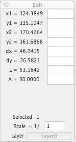
This is the Edit pallet for drawing lines. Here it is showing the data for the red line in the example below. When you click on the drawing with one of the Line Tools, the left-hand part of the pallet will fill with live data until you have completed the line. After you have drawn the line, clicking it with the Select tool will display the data and you can edit it in the right-hand boxes. The positional data (x1, y1, x2, y2) is relative to the zero point of your drawing which by default is the top left hand corner – but you can change this – see Preferences >> Display.
 Here we have the red line, drawing it from top left to bottom right.
x1: Start point on the x-axis.
y1: Start point on the y-axis.
x1: End point on the x-axis.
y1: End point on the y-axis.
dx: x-axis distance.
dy: y-axis distance
L: Line actual length.
A: Line angle.
Selected: The number of objects selected.
Scale: The scale the line is drawn at.
Layer: The layer the line is drawn on.
 Tip: Angles show as the absolute angle counting clockwise, so our red line shows 30º. This is with positive y downwards (the default). If you select for positive y upwards, then angles will count anti-clockwise (and A would show as 330º), and y1, y2 and dy would be negative.
Tip: The Layer box is dimmed if the selected object is on the active layer; it changes to undimmed if the selected object is not on the active layer, in which case clicking the Layer box will move you to the layer the object is on, and make that the active layer.
To edit the data, type the required new data in the appropriate box and hit the Enter key. Most commonly with a line you will want to edit the length and/or angle, but you can edit any of the data.
Tip: From Version 4.80 the Length box is automatically on focus when a line is selected. This means that you can immediately specify the length of a line after you have drawn it, without clicking in the Length box in the Edit pallet – just draw the line and immediately type in the length. Or if you want to change the length of a line drawn earlier, just select it and immediately type the length. You can also immediately use mathematical functions (=, (), +, -, *, /)
Tip: You can also use mathematical functions (=, (), +, -, *, /) in the all the data editing boxes. For example suppose you want the red line to be one-and-a-half times as long, you can type *1.5 in the length data box. RealCADD will multiply the existing length of the line (as shown in the left-hand data figures) by 1.5 and extend the line (in the direction it was originally drawn) to the new length. Or another example, to change the angle by 5º you could enter +5 in the angle data box.
Tip: You can change the length of more than one line at once – suppose you want to extend several lines by 40mm, all you need to do is select the lines to extend and enter +40 in the length box – all the lines will be extended by 40mm.
Tip: Lines extend or shorten in the direction they were originally drawn. If you want to change their length in the opposite direction, select the line and hit ⇧⌘H, ⇧⌘V to reverse an angled line – if it is horizontal you just need to hit ⇧⌘H – or ⇧⌘V if it is vertical. Then enter the data to change the length.